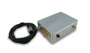
Splitterbox
The splitterbox is a small FPGA-based timing board which helps to prevent false trigger conditions and correct them if possible. If one wants the splitterbox to be integrated into our system it will be built into the front-panel of the powersupply. If that is not necessary it will be connected to the 24V connector on the backside of the powersupply. The functionality of the splitterbox is controlled by 28 small DIL switches inside the Box.
Functionality
| Singlepulsecontrol | The rising ede acts as ‘on’ trigger, the falling edge as ‘off’ trigger |
| Dualpulsecontrol | The ‘on’ trigger selects whether a ‘on’ or ‘off’ trigger is generated at a rising edge of the ‘off’ trigger |
| Split | The ‘on’ and ‘off’ trigger events are routed to one of the four outputs in a specific order. Four different modes are available |
| Gate | The inputsignals can be gated by a TTL signal |
| Maximum Pulsewidth | The maximum time difference between a ‘on’ and ‘off’ trigger can be set. |
| Triggerwidth | The pulsewidth of the triggersignals can be set. |
| Retrigger | The splitterbox retriggers or resets the switch after a certain time period |
| Dual Input | The ‘off’ input is used as a second ‘on’ signal. It is not gated. |
| Differential Switch | If a differential switch is connected at the output this switch deactivates the lower limit of 50ns between ‘on’ and ‘off’ trigger events. |
If any other fuctionality is needed feel free to ask for a special version of the splitterbox
General Specifications
| Inputs | Level | 0 to 5V, 10ns pulsewidth into 50 Ohm, Schmitt-Trigger |
| Jitter | Input to Output: 250ps | |
| Output to Output: 25ps | ||
| Max. operating Frequency | 50MHz | |
| Ouputs | TTL 0 to 5V into 50 Ohm, | |
| Risetime 1.2ns | ||
| Power Input | 24V DC |


