Timeshifter
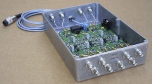
The timeshifter is a small device used to delay up to four triggersignals by the use of up to four analog control signals. The polarity of the voltage vs. delay function as well as the analog voltage source for each channel can be selected individually.
General Specifications
| Power Input | 24V DC | |
| Analog Input | 0 to 5V | |
| Trigger Input | Level | TTL, 0 to 5V |
| Termination | 50 Ohm | |
| Trigger Ouput | Level | TTL, 0 to 5V |
| Load | 50 Ohm | |
| Risetime
|
<1.2 ns
|
Description and Use
Applying voltage to a Pockels cell arranged between two beam splitting polarizers as shown in figure 2 below, will deflect part or all of the laser radiation at the second polarizer. The voltage necessary to deflect all of the laser radiation at the second beam splitting polarizer varies typically from less than a kilovolt up to 10 kV.
Clearly, if the voltage applied to the Pockels cell is varying with time, the power deflected at the second beam splitting polarizer will vary with this time varying voltage. Using a continuous wave laser radiation, and applying a short voltage pulse to the Pockels cell will lead to a short optical pulse behind the second polarizer, as shown in the figure below.
Varying the optical power contained in this optical pulse can be done in two ways:
a) By varying the voltage applied to the Pockels cell. This means, changing the supply voltage of the Pockels cell driver. Typical high voltage power supplies can change their voltage levels on time scales of milliseconds, the fastest achievable is on the order of a few 100 microseconds.
b) by changing the time position of the level change. This can be done from pulse to the next, after 100nsec, 50nsec, or even after 10nsec.
The figure below shows an optical pulse of larger temporal width as before, hence transporting more optical energy.
Varying the optical power contained in picosecond or femtosecond pulses is even more simple. As figure 5 below shows, all that needs to be done is shift the optical transmission pulse of the of the Pockels cell, polarizer arrangement relative in time to the short laser pulse. Figure a shows the situation where the maxima of both pulses coincide, and Figure b shows the optical transmission pulse, viz. the voltage pulse on the Pockels cell shifted to some later time, reducing the amplitude of the transmitted laser pulse.
Figure 6 shows a schematic representation of this energy control method: The transmission time of a trigger pulse through a circuit is modified by an analog voltage also applied to this circuit. The Time Shifter box shown at the top of this page actually has four such delay circuits, two of them could be used to modify the timing in a Pockels cell driver using a push-pull high voltage switch, four would be necessary to have time control over all trigger signals in a Pockels cell driver based on a bridge circuit.